
The safety level of rail transport is relatively high compared to other types of transport, thanks to numerous safety precautions and system-related safety mechanisms.
To maintain this level of safety, new vehicles are subjected to type testing in accordance with the mandatory regulations before they are approved for service.
Access deeper industry intelligence
Experience unmatched clarity with a single platform that combines unique data, AI, and human expertise.
Given this, dynamic running tests performed by third-party inspection and assessment bodies are an indispensable part of the approval process and must be taken into consideration during the development of new rail vehicles.


Using simulations, for example, driving dynamics can be optimised early in the development process. According to new regulations such as the EN 14363:2019 standard, the data gained from simulation can replace the data gained from conventional measurement, at least to some extent.
This, in turn, may reduce the duration of cost-intensive on-track tests designed to ensure that the train neither derails nor causes displacement or other overloading of the track.
What is important in track testing? A rail vehicle passing through a track curve is exposed to acceleration forces that act transversely to the direction of travel (centrifugal acceleration).
The level of these acceleration forces depends on the curve radius and vehicle speed. The route sections of the rail network operator that are needed for the test must be selected and evaluated as early as the planning stage of the test.
An ideal test track includes both straight sections and numerous curves of varying radii, to cover as many areas of the test as possible and avoid the necessity of changing to another route. The exact characteristics and the minimum length of the test track depend on the rail vehicle’s approval parameters.
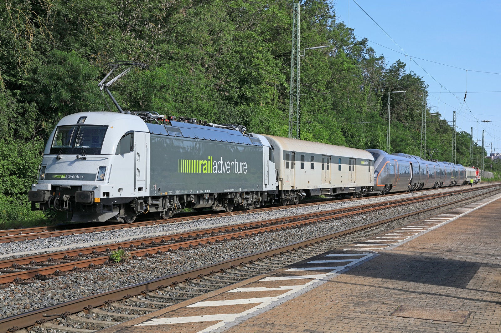
Case study: Test run under “Norwegian conditions”
Testing of a Norwegian high-speed train by RailAdventure, a Munich-based company specialising in rail test runs, underlines how the exact characteristics and the minimum length of the test track depend on the approval parameters of the rail vehicle in question.
The train to be tested was to be approved for a maximum speed of 245 km/h. Given this, the train had to navigate curves with radii of less than 3,000 metres at a speed of approximately 270 km/h.
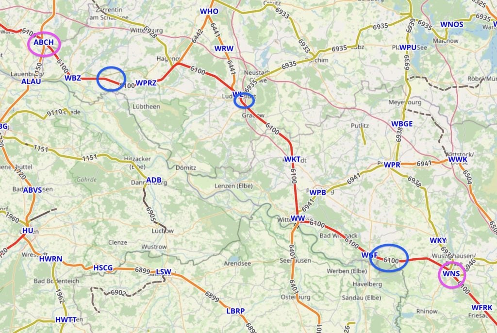
After intensive discussions with the rail network operator, curves with the radii required by the standards were found in Germany. However, the overhead line system on that section of the rail route was only approved for a maximum speed of 230 km/h.
The problem, in this case, is that high speeds have a significant impact on the pantograph’s contact force, and thus ultimately on the uplift of the contact wire. An excessive increase in uplift, in turn, can damage the overhead contact line.
To make matters even more complicated, the Norwegian train exceeded the German standard gauge and did not have train safety equipment on board based on German signalling systems.
RailAdventure, therefore, needed to establish and prove to the rail network operator that it was safe to exceed the maximum speed permitted on the route in the test. Working with the experts from its project partner, TÜV SÜD Rail, and in close collaboration with the rail network operator, RailAdventure developed a concept to enable the test runs to take place.
Simulations and on-track tests
In a first step, the experts had simulation analyses carried out to analyse and evaluate the interaction between the pantograph and the overhead contact line. Once the green light had been given for the on-track test, the rail professionals then had to make sure that the uplift of the contact wire remained within tolerable limits.
As uplift is determined on the basis of stationary measurements taken at only a few points along the route, the points selected had to be representative of the route as a whole. To identify these critical points, the experts used data from a catenary measuring vehicle that regularly inspects the entire line.
Working with the manufacturer and carrying out tests on a route approved for this speed, the experts then optimised the pantograph, which had a Norwegian profile (1800 mm wide instead of 1950 mm), so that the forces occurring at a speed of 270 km/h were identical to those during regular running at 230 km/h.
Taken together, all of these actions optimised pantograph behaviour in such a manner that the contact wire uplift remained within the permissible limit even at the most critical point along the route.
As a further safety measure, the test runs were undertaken in single traction with a single pantograph, thus minimising the wave motion of the overhead contact line compared to a run conducted with multiple raised pantographs.

Following these optimisation measures, the running tests were performed on the selected route. After initial runs at 230 km/h, the maximum speed permitted on the route, the testers gradually increased velocity up to the train’s maximum speed of 270 km/h, while closely monitoring the values measured at the contact points with the rail and overhead contact line.
The values measured revealed that at lower speeds, the contact force now fell short of the minimum values defined in the standards. As a result, the pantograph settings for normal operation had to be readjusted after these tests to ensure that the pantograph complies with all approval-relevant limit values.
The special aerodynamic optimisation of the pantograph proved particularly critical for ensuring the contact force between the contact strip and the contact wire was set precisely for the test runs.
All actions together enabled the required on-track test to be completed without exposing the pantograph, the overhead contact line or the route itself to excessive loads or damage. The Norwegian train was thus successfully approved, even though no suitable route had originally been available.